The main objective of this study is to investigate into the six-cylinder water raising pump described around 1550 by the Ottoman Muslim scientist Muhammad Ibn Ma'ruf, known as Taqi al-Din, in his treatise Al-Turuq al-Saniya fi al-' alat al-ruhaniya. After an outline of the historical context and an English translation of the relevant sections of the manuscript, the focus is laid on the engineering analysis of the water pump. The result of the analysis yielded the reconstruction of the machine through a graphical model which was then used to produce a virtual 3D animation of the mechanical workings of the various parts, including the water turbine, the cam shaft, the connecting rods, the reciprocating pistons and the cylinders.

Salim T S Al-Hassani* and Mohammed A. Al-Lawati**
Table of Contents
1.1. Preface
1.2. Structure of the Article
1.3. Nomenclature
2. Water Machines in the Lands of Islam
2.1. The Science and Art of Water Management
2.2. Three Water-Raising Machines in Al-Turuq al-Saniya
2.2.1. The Pump with Two Opposing Cylinders
2.2.2. The Spiral Pump
2.2.3. The Pump of the Rope with Cloth Balls
3. Taqī al-Dīn and his Treatise: Historical and Textual Context
3.1. Overview on the Treatise Al-Turuq al-Saniya
3.2. Description of the Pump with Six Cylinders
4. The Functioning of the Pump: Technology and Operation
4.1. How Does it Work
4.2. Historical Assessement of the Six-Cylinder Pump
5. Mathematical Diagnostics of the Six-Cylinder Pump
5.1. Pipes, Cylinders and Pistons
5.2. The Connecting Rod, the Pivot and the Cam
5.3. Complementary Parts
6. Virtual Reconstruction of the Pump
6.1. Modelling and Animation
6.1.1. Modelling
6.1.2. Creating Objects
6.1.3. Modifying Objects
6.1.4. Assigning Materials
6.1.5. Creating Lights and Cameras
6.2. Animation
6.3. Computer Softwares
6.3.1. MathCAD
6.3.2. 3D Studio MAX
6.4. The 3D Model
6.5. By Way of Conclusion
6.6. Acknowledgments
7.1. The Evidence from the Manuscript
7.2. References
* * *
1.1. Preface
 |
|
|
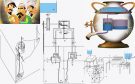
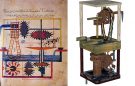
Figure 1: Drawing of the six-cylinder pump as it was depicted in Taqī al-Dīn in Al-Turuq al-Saniya fī al-’ālat al-rūhaniya (Chester Beatty Library in Dublin, Arabic MS 5232, p. 38). |
The main objective of this study is to investigate into the six-cylinder water raising pump described around 1550 by the Ottoman Muslim scientist Muhammad Ibn Ma‘rūf, known as Taqī al-Dīn, in his treatise Al-Turuq al-Saniya fī al-’ālat al-rūhaniya. Our study of this important machine consists of three major parts. The first covers some historical facts that give knowledge about the role of engineering and engineers. The second is centered on an engineering analysis of the water pump. The last obtains all the dimensions of the machine and provides a graphical model which was then used to produce a virtual 3D animation of the mechanical workings of its various parts, including the water turbine, the cam shaft, the connecting rods, the reciprocating pistons and the cylinders. The study is focused on the pump in order to verify its ability to work using modern engineering analysis.
1.2. Structure of the Article
The study is composed of seven sections. The first one is introductory whilst the layout of the remaining sections is as follows. The second chapter contains a historical background about the Islamic tradition of engineering and water raising machines. The glimpses we present about Islamic engineering give an idea of how engineering was practiced and what were the working fields for engineers. Our aim in this short survey is to know how metals and some other materials were obtained or manufactured. This will help to decide the type of the material and select the suitable mechanical properties for it.
The third section presents a concise biographical sketch about Taqī al-Dīn and the contents of his treatise, with the English translation of the relevant portions on the pump from the original manuscript. The fourth chapter explains the working of the device. The fourth and fifth sections represent the core of this study as they describe the machine and its components, explain its mechanical function and the various materials used.
 |
|
|
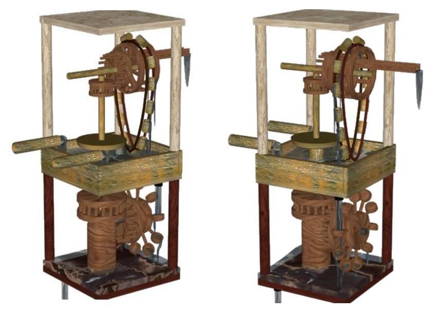
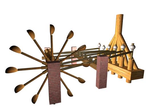
Figure 2: Parallel views of the virtual reconstruction of the pump. |
The fifth section is mainly devoted to mathematical analysis to verify the mechanical adequacy of the different components. This analysis and related calculations show how robust the pump was, and whether it was capable of delivering the water to the required height. All the equations and formulas in this section were obtained from the sources (3), (4), (5), (6) and (9) [see the list of references in Appendix 7.4]. The values for some physical constants such as the coefficient of friction and the drag coefficient were found in the Data Book of the Department of Mechanical Engineering, UMIST, Manchester , UK.
The sixth section covers the modelling and animation part. Modelling the pump and animating its motion gives a better insight of its operation and helps to properly understand its operation and the linkages and dimensions of each component. This section ends on a conclusion drawn from the research and also contains suggestions for further work.
Finally, the last section is devoted to appendixes: a reproduction of the three pages of the original manuscript and a list of the main references used in the study.
 |
 |
|
Click here to view animation. |
Click here to view animation. |
1.3. Nomenclature
In this section, we present the list of symbols assigned to the different physical and mathematical magnitudes involved by our description of the six-cylinder pump.
| d | Distance between the centers of two holes |
| di | Horizontal distance between the center of pipe i to the center of collective pipe |
| ai, bi and g | Variable angles |
| ω | Angular velocity |
| dD | Diameter of delivery pipes |
| dP | Diameter of piston cylinder |
| dC | Diameter of Collective pipe |
| dS | Diameter of suction pipes |
| dPR | Diameter of piston rod |
| dCR | Diameter of connecting rod |
| dlever | Diameter of wheel lever |
| dcam | Diameter of cam |
| hD | Height of delivery pipes |
| hP | Height of piston cylinder |
| hC | Height of collective pipes |
| hS | Height of suction pipes |
| hCB | Height of cylinder block |
| ρwater | Density of water |
| ρwood | Density of wood |
| G | Gravity |
| π | Pi |
| VC | Volume of collective pipe |
| VD | Volume of delivery pipe |
| Vcone | Volume of conic pieace |
| VP | Volume of piston cylinder |
| VCS | Volume of Camshaft |
| Vlever | Volume of wheel lever |
| Vscoop | Volume of scoop |
| Ff | Friction force |
| FD | Heighest water force in the delivery pipes |
| FC | Water force in collective pipe |
| Fcone | Water force in conic pipe |
| FW | Total water force in all three pipes |
| Fcam | Force on cam |
| Arm | An old measurement; measures about 70 cm |
| Span | An old measurement; measures about 1/3 of an arm (≈ 23 cm) |
| llever | Length of wheel lever |
| lPR | Length of piston rod |
| lcam | Length of cam |
| lCB | Length of cylinder block |
| WL | Weight of lead |
| Wcs | Weight of camshaft |
| Wwheel | Weight of wheel |
| rPR | Radius of piston rod |
| rCS | Radius of camshaft |
| Re | Reynolds number |
| D | Drag force |
| M | Moment |
| Twood | Shear stress of wood |
2. Water Machines in the Lands of Islam
2.1. The Science and Art of Water Management
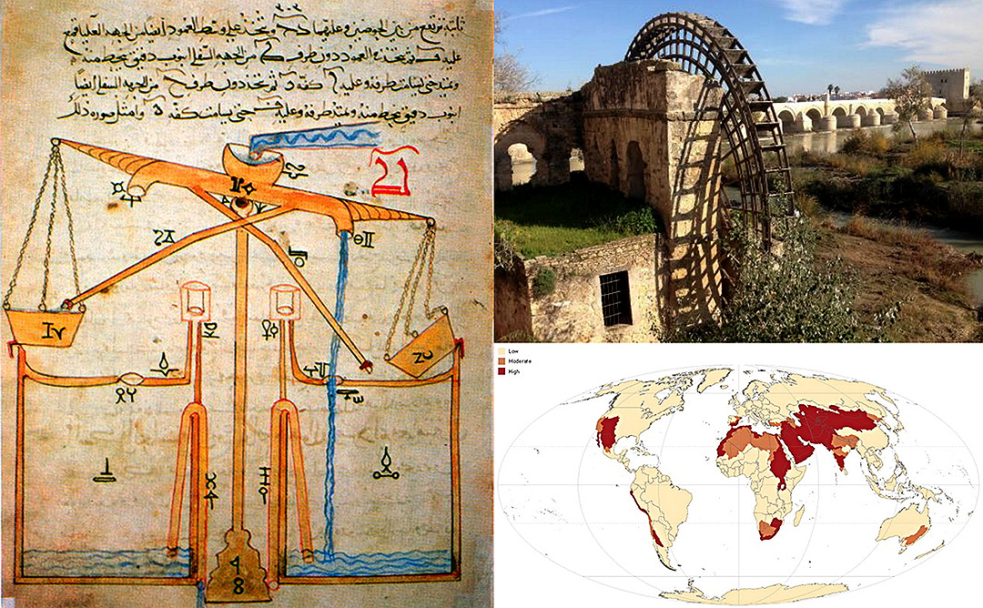
The use of water wheel technology was widely spread in the Middle East before Islam. It is from this long lasting heritage that Muslim engineers adopted and improved this technology and applied it everywhere. In the city of Murcia, for example, during the Islamic rule of Spain, a waterwheel was established, still known today under the name La Ñora. Although the original wheel has been replaced by one in steel, the original system applied during the Andalus period is otherwise virtually unchanged. The flywheel mechanism, which is used to smooth out the delivery of power from a driving device to a driven machine, was invented by Ibn Bassal (fl. 1038-1075) who pioneered the use of the flywheel in the chain pump (saqiya) and noria [1].
The industrial uses of watermills in the Islamic world date back to the 7th century, while horizontal-wheeled and vertical-wheeled water mills were both in widespread use by the 9th century. A variety of industrial watermills were used in the Islamic world, including gristmills, hullers, paper mills, sawmills, shipmills, stamp mills, steel mills, sugar mills, and tide mills. By the 11th century, every province throughout the Islamic world had these industrial watermills in operation, from al-Andalus and North Africa to the Middle East and Central Asia. Muslim engineers also used crankshafts and water turbines, gears in watermills and water-raising machines, and dams as a source of water. They used to provide additional power to watermills and water-raising machines. Industrial water mills were also employed in large factory complexes built in al-Andalus between the 11th and 13th centuries.
Muslim engineers used two solutions to achieve the maximum output from a water mill. The first solution was to mount them to piers of bridges to take advantage of the increased flow. The second solution was the shipmill, a type of water mill powered by water wheels mounted on the sides of ships moored in midstream. This technique was employed along the Tigris and Euphrates rivers in 10th-century Iraq, where large shipmills made of teak and iron could produce 10 tons of flour from corn every day for the granary in Baghdad [2].
Early examples of water raising machines include the Shādūf, the Sāqiya and the Noria [Nā‘ūra], all of which were known in the Muslim world [3]. At an early stage Muslim engineers were exploring new methods for increasing the effectiveness of water raising machines. Al-Jazarī and Taqī al-Dīn both described water-raising machines that show an awareness of the need to develop machines with a greater output than these traditional ones. By the 13th century, what we might call water raising machine technology lifted off with the work of al-Jazarī. In his monumental book Al-Jāmi’ bayna ‘l-‘ilm wa-‘l-‘amal nāfi‘ fī sinā‘at al-hiyal, this genius scholar was responsible for the design of five machines for raising water. The most significant is the fifth one, which was a water-driven pump. A water wheel turned a vertical cog wheel which in turn turned a horizontal wheel; the latter caused two opposing copper pistons to oscillate. The cylinders of the pistons were connected to suction and delivery pipes which were guarded by one-way clack valves. The suction pipes drew water from a water sump down below and the delivery pipes discharged the water into the supply system about 12m above the installation. This pump is an early example of the double-acting principle (while one piston sucks the other delivers) and the conversion of rotatory to reciprocating motion [4].
Taqī al-Dīn describes a slightly modified version of al-Jazarī’s fifth machine in his book on machines Al-Turuq al-Saniya.
2.2. Three Water-Raising Machines in Al-Turuq al-Saniya.
2.2.1. The Pump with Two Opposing Cylinders
This pump, already dealt with by Al-Jazarī, is a unique mechanical device that may be considered as a major achievement in the history of mechanical engineering. Historians considered that al-Jazarī’s machine was the archetype from which the steam engine was developed [5].
Because all figures and drawings in the manuscripts of Al-Jazarī’s book contained mistakes done by scribes, historians of technology could not reach an agreement on the correct design of the machine. This is why Taqī al-Dīn’s description of this pump has a greater historical value, as the figure which he drew himself was accurate and helped remove obscurity that surrounded parts of this machine.
Taqī al-Dīn’s description of this machine in his treatise is accompanied by a drawing (fig. 3) that combines both the tools of conic sections and perspective drawing. This is why drawings are difficult to read and understand, and it becomes imperative to read texts carefully to arrive at a correct conception of the model.
 |
|
Figure 3: Drawing of the reciprocating pump with two opposing cylinders (Chester Beatty Library in Dublin, Arabic MS 5232, p. 32). |
2.2.2. The Spiral Pump
The description of the spiral pump in Al-Turuq al-Saniyah is very significant because it was not mentioned in the Arabic books of engineering before Taqī al-Dīn. The use of spiral in mechanical devices is attributed to Archimedes and it was largely used around the Mediterranean. We do not, however, find any description of a spiral pump machine in the available references written before Taqī al-Dīn (fig. 4) [6].
Taqī al-Dīn’s spiral pump is worked by a waterwheel through two cogwheels each fitting into the other. It seems, according to historians of technology, that the earliest description of this kind of machines in the West goes back to Cardan in 1550 and Ramelli in 1588. This means that Taqī al-Dīn was amongst the first to describe this water machine as he finished his manuscript in 1551-52 (959 H). The use of spiral pumps flourished in Europe after this period, especially in drainage projects, before they came into common use in the 17th and 18th centuries and were turned by wind as well [7].
 |
|
Figure 4: Drawing of the spiral pump (Chester Beatty Library in Dublin, Arabic MS 5232, p. 34). |
2.2.3. The Pump of the Rope with Cloth Balls
No description of this pump was given before Taqī al-Dīn. Moreover, as far as we know Taqī al-Dīn preceded Western engineers in describing it. Agricola mentioned a similar device in De re metallica which (completed in 1553 and published three years later), namely few years after that that our Muslim engineer completed Al-Turuq al-Saniya.
The pump of the rope could get water raised from great depths up to 72 metres (fig. 5). In contrast, pumps with pistons can raise water to small heights only, as they are limited by air pressure. Therefore, the alternative is to use a rope or chain that carries buckets or to use a pump of a robe with cloth balls. The cloth balls move tightly in a vertical tube. These balls are spaced at equal distances and fastened to a rope or chain. When the balls move upwards inside the tube, they behave like a piston in cylinder as it pulls water up [8].
 |
|
Figure 5: Drawing of the pump of the rope with cloth balls (Chester Beatty Library in Dublin, Arabic MS 5232, p. 35). |
3. Taqi al-Din and his Treatise: Historical and Textual Context
The real name of our scholar is Muhammad Ibn Ma‘arūf, but he was nicknamed Taqī al-Dīn. He is more known under this kunya. Al-Rāsid is often added to his name to attest his main scientific interest in astronomy and his fame as founder and director of the Istanbul observatory (1575-1580). Taqī al-Dīn was born in Damascus as he mentioned it in his book Al-Turuq al-Saniya. He was born in 1525/1526, and he died in Istanbul in 1585 [9].
3.1. Overview on the Treatise Al-Turuq al-Saniya
The book of Taqī al-Dīn Al-Turuq al-Saniya fi’1-ālāt al-rūhaniyya was written in Damascus about 1551. Its manuscript copy held in Chester Beatty Library in Dublin is dated back to 1551-52 (959 H), and the title page indicates that it was reviewed a year later by a student. The treatise, which is not yet translated into English, contains descriptions and illustrations of clocks, weight-lifting equipment, pumps and various other machines. It survived in several manuscript copies preserved at different libraries throughout the world: Dār al-kutub al-misriya in Cairo (MS Falak 3845, Miqat 557/4), Chester Beatty Library in Dublin (MS 5232), the library of Kandilli Observatotry in Istanbul (MS 96, autograph). In 1976, Ahmad Yusuf al-Hassan published an offset reproduction of the Dublin’s manuscript copy, that he accompanied with a thorough study[10].
The treatise includes six sections dealing in order with:
In this work, Taqī al-Dīn focuses on the geometrical-mechanical structure of the machines, following the method of analysis used previously by the Banū Mūsā and Al-Jazarī. The machines described in the book can be summarised as follows:
1. The Moon pot or the Moon box: It is an astronomical clock known in Arab mechanical technology as pointed out by Taqī al-Dīn himself in his other book of mechanics Al-Kawākeb al-durriya fī ‘l-bankāmāt al-dawriya (The Luminous Stars in Mechanical Clocks).
2. A series of four types of clocks, including water clocks and sand clocks.
3. Weight-moving machines including a lifting-apparatus worked by gears (crane), a tool worked by ropes and reels, and another one worked by a spiral.
4. Water-Raising Machines: several types of water-raising machines to which a whole section is dedicated. They include: the pump with two opposing cylinders, the spiral pump, the pump of the rope with cloth balls, and the six-cylinder pump.
5. Making a fluting machine, taps and fountains.
6. Sundry subtleties: they contain the description of eleven tricks such as the water-carrier, the two cups of justice and injustice, the sailor’s boat and others. Similar tools were also described in the books of Banū Mūsā and Al-Jazarī.
7. A Machine that automatically rotates a spit that carries meat over fire: It represents the working of a rudimentary steam engine and steam turbine, predating the more famous discovery of steam power by Giovanni Branca in 1629 [11].
3.2. Description of the Pump with Six Cylinders
In the following section, we provide information about the pump with six cylinders. A clear investigation in the pump will take place. Many questions will be answered here such as: how does it work? What is it made from? And how efficient it is? The best way to start investigating and understanding this pump is to read the description of Taqī al-Dīn himself. Then, when his description is not clear and detailed enough, we search for details from some other sources that were written in the same period of time. The section will contain a translation of Taqī al-Dīn’s description, done from the Arabic text of Al-Turuq al-Saniya. The description of the six-cylinder pump holds on three pages in the manuscript of Chester Bettay Library in Dublin (MS 5232, pp. pp. 36-38) (see fig. 21, 22 and 23).
Taqī al-Dīn described the pump long time ago, so the language he used might be difficult to understand. However, his description was translated without changing the style. The explanations are written into brackets within the text. He said:
“Take a block of wood two arms long and divide it into six identical divisions. Make in each division two circular holes one of them passes through to the other side and the other side [suction hole] and the other does not pass through but turns and meets the first hole [delivery hole]. Make below all the holes that pass through a frieze on a top of it a tight lid [clack valve], as it was mentioned in the first section of this chapter. Then make six pipes of wood or iron [delivery pipes] and fit underneath each one a frieze on a top of it a tight lid as mentioned [clack valve] and fit them on the top of each hole of the holes that does not pass through so that the frieze becomes at the bottom and fit on each hole of the holes that pass through a proper pipe with identical ends and middle hole each is one span long [piston cylinder]. Make an iron bar for each one (piston rod) and make at his end two small metal disks wrapped between them a lubricated string of cannabis as mentioned before [piston] and in it’s other end a hole and fit it in the pipe properly after you turn the ends of the long pipes to each other and equate them horizontally and fit above them a collective pipe for them all and make it as long as you want the water to reach. Then put this block in the water and fix it from its sides and make opposite each head a crosspiece and put on the two crosspieces a parallel bar [pivot bar] to the bar ends in the pipe. Then make six hands of iron with a hole in the middle and at one end [connecting rods]. Fit the holes at the end in the bars and the holes in the middle in nails fitted on the crosspiece [pivots]. Then fit at the end of each standing bars in the six pipes [piston rods] a weight of lead weighs more than the water that fills in the long pipe that takes the water upwards so that if the pipe got filled with water and the bar was up, the lead pushes it until it rises in the long pipe the same amount that the bar moves down. Then make opposite to each crosspiece another one. Make on them a hexagonal bar [camshaft] with two axes in its ends that rotate smoothly and it has to be parallel to the ends of the hands [connecting rods]. Then, fit on it’s side a big wheel. Then make in one of the faces of the hexagonal axis an apparent tooth [cam] nailed in it. It has to be parallel the first hand [connecting rod] so if the wheel rotated to the hands side, the tooth pushes the hand so the bar with the weight rises completely. And when it is released, the bar falls because of the lead weight. Then make in the next face of the hexagonal bar another tooth parallel to the third hand and so on until the sixth hand. As its clearly obvious that if the wheel rotated to the hands side, the first tooth pushes the first hand. So when the bar is lifted up it pulls the water because the lid [piston] is fitted tightly on the pipe. And if it is been released it’s the pushes so it rises in the pipe. And Its also known that whenever one of the hands was released from it’s tooth [cam], the other caught so the water flow from the collective pipe becomes continuous and it is one of the proper methods but it’s the best and this is it’s picture.
Its obvious that its work with six pipes is not necessary as it is possible with one pipe and the required may be achieved by the water flow. But it is preferred that it is not to be with less than three pipes so the water flows in a continuous manner and that could be achieved by two pipes as it can be seen; and Allah knows best [12].”
4. The Functioning of the Pump: Technology and Operation
4.1. How Does it Work
Taqī al-Dīn’s description explained how the pump works, but it was not that clear. The way how the pump works must be understood properly before analysing it. Let us start explaining it again more clearly. The best point to start with would probably be the input power source which in this case is the river, to the resultant output, which is the delivered water. The river exerts a force on the scoops, which represent the drag force. This drag force causes the wheel rotate and with it the cam shaft to rotate. But as in any mechanical system, there must be a friction force against any motion. The friction force here is due to the end bearing between the camshaft and the supporting stone wall. So the total force exerted on the wheel will be the difference between the drag force and the friction force. Each cam pushes the corresponding connecting rod causing its proximalend downwards and the distal end upwards lifting lead weight upwards, which consequently pulls the piston sucking the water from the river through the inlet clack valve. As the camshaft rotates further, the cam releases the connecting rod, and the the piston’s stroke ends. Then the piston is pushed downwards by the shear weight of lead weight and pushes the water upwards through the vertical outlet pipes. As mentioned earlier, the clack valve closes when the water moves in this direction, so the water is forced to go through the other hole and through the delivery pipes. There is another clack valve at the bottom of each delivery pipe that prevents the water from going back again to the piston cylinder (see fig. 6).
 |
|
|
Figure 6: The six-cylinder pump at work in the river. |
4.2. Historical Assessment of the Six-Cylinder Pump
The six-cylinder pump is undoubtedly the most important water machine described by Taqī al-Dīn. He felt this himself, so he said at the end of his description of it: “This is an immaculate method. It is more perfect than any of the previous ones”.
To assess Taqī al-Dīn’s achievement, let us draw a brief picture of the pump technology in Europe in the same period. It is well known that pumps were a subject of interest for engineers in the 16th century in Europe than during the medieval times and more importance was even given to the sucking piston pump. No new pumps were invented but many changes were made to old designs in this period. The most important relevant books of machines published in the 16th century were those of Agricola (De Re Metallica, 1556) and Ramelli (Le Diverse et Artificiose Machine, 1588). In these books, the two Italian engineers described several types of pumps, and for some historians this mechanical advancement led to the invention of the steam engine by Newcomen in 1712. This invention was truly a great victory for mechanical engineering [13].
If we take all these facts into consideration and start to study Taqī al-Dīn’s six-cylinder pump, before Agricola and Ramelli, we realise the historical importance of his invention. This importance becomes even clearer when we know that no machine similar to Taqī al-Dīn’s pump was described either by Agricola or Ramelli.
Although the mechanism of the cam or the mechanism of the trip-hammer was known to the Chinese, however, Taqī al-Dīn’s design has the following features:
1. Using the cylinder block for six cylinders in one line for the first time. This is a modern and advanced mechanical technique relative to his time. It can be said that this pump is the direct grandfather for the modern six cylinder engine in-lined in one row and made in one piece.
2. Using the camshaft with six cams distributed in order on the circumference of the circle so that the cylinders work continuously and the flow of the water as well. Taqī al-Dīn advises that the number of the cylinders should not be less than three. And this advanced understanding for the continuity besides the modern mechanical balancing is what led to manufacturing the modern multi-cylinders engines and compressors.
3. Although the idea of gravity driven piston is old, however, this water piston was the one that affected future engineering.
Taqī al-Dīn, contrastingly, made a lead weight on top of each piston rod that outweighs the water column inside the pipe. He said: “On top of each of the vertical rods that were fixed to the six tubes, put a lead weight that outweighs the water going through the long pipe towards the discharge point.”
There is a parallel design in the pump made by Samuel Morland (1625- 1695), the English academic and inventor credited with early developments in relation to computing, hydraulics and steam power. In 1675, Moreland patented a ‘plunger pump’ capable of “raising great quantities of water with far less proportion of strength than can be performed by a chain or other pump”. He used lead disks above the piston so that the piston is forced down by the weight pushing water up to the desired height [14]. Obviously the patent office miss out the precedence of Taqi al-Din’s lead weight driven piston and pump.
5. Mathematical Diagnostics of the Six-Cylinder Pump
The previous section showed how the pump works in general. Now let us move further to the calculations. We start from the delivered water.
Because this pump has many mechanical parts, it is divided into small sections as shown in figure 7. Each system is studied separately and the results from each are processed and then integrated for the whole pump.
 |
|
Figure 7: The pump divided into three sections. Source: A. Y. Al-Hassan and D. R. Hill, Islamic Technology: An Illustrated History (Cambridge, 1986, p. 51). |
Now that the pump has become a combination of three small mechanical systems, each system can be studied separately and then the results from each system can be processed to give final results for the whole pump.
5.1. Pipes, Cylinders and Pistons
Section 1 of the pump consists of the collective pipe, the delivery pipes, the cylinder block, the suction pipes, the piston cylinders and the lead weight. The dimensions of the pump that were given by Taqī al-Dīn were too few and were not enough to analyse the pump. Only the length of the cylinder block and the height of the piston cylinders were given by him. All other dimensions are to be as much as needed, according to what he said. Let us see if it is possible to estimate the other dimensions by knowing those two dimensions only. We first list the knowns and the unknowns and develop the equations needed to determine the unknowns.
Unknowns:
Height of delivery pipes
Hole diameter
Distance between holes
Weight of lead
Piston rod diameter.
There are more unknowns than equations. Hence some independent dimensions have to be guessed guided by the facts provided from Taqī al-Dīn’s description and the historical research. In this case, most dimensions are flexible except the two mentioned above. However, some other dimensions can be assumed that they are fixed for this particular analysis. Taqī al-Dīn said in his description that the cylinder block is to be divided into six equal parts so each part will be:
d = 1400 / 6 = 233mm
Taqī al-Dīn said that the length of the cylinder block is to be about two arms, so for the ease of calculations let us round d to 250mm and change the cylinder block’s length to:
LCB = (6). (0.25) = 1500mm
By looking at Taqī al-Dīn’s drawing in appendix 7.1 (Chester Beatty Library in Dublin, Arabic MS 5232, p. 37), the diameter of the holes can be estimated. Setting the diameter at 100mm makes this part of the pump Wilmore like the one in his drawing. Now assume that the cylinder block is divided into two equal horizontal parts and the distance between the six holes in a row is the same as the distance between the two rows which is 250mm. Then the width of the cylinder block will be:
WCB = (2) . (0.25) = 500mm
 |
|
|
Figure 8: Top view of the pump. Source: A. Y. Al-Hassan and D. R. Hill, Islamic Technology: An Illustrated History (Cambridge, 1986, p. 51). |
The height of the cylinder block depends on the hole diameter as well. Let us assume that it is 180mm. Because the cylinder block will be placed on a water stream , the suction pipes do not have to be that long. Let us assume that they are 100mm long. The height of the delivery pipes should be flexible, because it totally depends on where the pump is going to be placed. But this height should be limited so that the maximum output of the pump can be determined. So let us think of the minimum and the maximum heights the pump can deliver water to. As it can be seen from figures 8 and 9, the lower the collective pipe the smaller the slope is needed to fit it in the conic pipe. The horizontal area will get bigger as well as it depends on the angle as shown in figure 7. As a result of this, the head force will increase. Besides, if the angle is too small, it is too difficult to join the delivery pipes with the collective pipes. So let us say that the minimum angle is 60°. This will be the angle of pipe 3. To find the angles of the other two pipes, the “flow chart” method is to be used to make it easier.
 |
|
Figure 9: Front view of the pump. Adapted from A. Y. Al-Hassan and D. R. Hill, Islamic Technology: An Illustrated History (Cambridge, 1986, p. 51). |
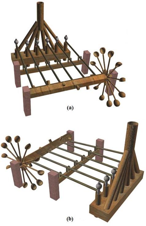
To find the distances d1, d2 and d3 the method of how the delivery pipes are going to be joined must be specified. Figure 10a-b shows a top view of a guess of how the pipes can be joined.
 |
|
Fig. 10a-b: Top view of delivery pipes. |
Because the three sides of both triangles abd and bcd in figure 10a are the same, then the triangles are equilateral. This means that all the angles equal 60°. In Figure 10b the angle g is:
g = b1 + b2
Using the law of cosine, ce can be obtained:
ce = [(eb)2 + (bc)2 – 2 · eb · bc · cos g]1/2
and the diameter of the collective pipe will be:
dcone = ce + dD / 2 = 182.288 mm
and
d1 = d / 2 – dD / 2
d2 = dD / 2 + d1 + d
d3 = d2 – dD + d
tan 60° = hD / d3 ⇒ hD = d3 · tan 60°
a1 = tan-1 hD / d1
a2 = tan-1 hD / d2
Assuming that the diameter of the collective pipe to be the same as that of any delivery pipe, the height of the collective pipe, after adding 50mm, will be 150mm, as shown in figure 11.
 |
|
Figure 11: Collective pipe. |
Now what happens if this height increased? According to Taqī al-Dīn, only the height of the collective pipe is to be increased. As it is known that the head force is proportional to the height as well as to the pipe diameter. So does the diameter of the collective pipe that was guessed earlier cause high forces? Let us think of the answer. As it was mentioned previously, the objective of this investigation is not to improve the pump but to analyse it. Because this pump lifts one piston at a time, according to Taqī al-Dīn, only the pipe that requires more force to lift the water through should be considered. After selecting this pipe, let us check if the assumed value for the collective pipe’s diameter was acceptable.
We need to ensure that:
(A*) (FD + Fcone + FC)1 < (FD + Fcone + FC)2
where subscript 1 means case 1, where the collective pipe’s height increases and subscript 2 means case 2, where the delivery pipe’s height increases.
The head force is:
FW = ρW · G · V
where V is the volume.
The volumes of pipes are:
Volume of conic pipe
Vcone = π / 3 · hcone · [(dcone / 2)2 + dcone · dC / 2 + (dC / 2)2]
Volume of collective pipe
VC = π · (dC / 2)2 · hC
Volume of delivery pipe
VD = π · (dD / 2)2 · hD
Volume of piston cylinder
Vp = π · (dp / 2)2 · hp
Upon substitution, equation (A*) becomes:
ρ · G · [VD / sin a3 + Vcone + VC]1 < ρ · G · [VD / sin a3 + Vcone + VC]2
[hD · (dD / 2)2 / sin a3 + hC · (dC / 2)2]1 < [hD · (dD / 2)2 / sin a3 + hC · (dC / 2)2]2
And so:
dC < [(hD)2 – (hD)1] · (dD / 2)2 / sin a3 + (hC)2 · (dC / 2)2
The diameter of the collective pipe can be anything but must satisfy the condition above.
The force required to lift the water will be:
FW = ρw · G · [VP + VD + Vcone + VC]
Taqī al-Dīn said that the weight of the lead must be greater than weight of the water (i.e. the force exerted by the water), which is true.
WL > FW
where WL is the lead weight and FW is the total water force. The lead weight will be calculated in the next section as some other dimensions needed.
Results from section 1:
MathCAD was used to perform the calculations. The input data and output results were obtained using this software. They are tabulated as follows:
| Input | Output |
| ρwater=994.1 kg/m3 | d1=0.125m |
| hcone=100mm | d2=0.425m |
| dcone=188.507 | d3=0.575m |
| Height=10m | hD=0.996m |
| a1=82.85° | |
| a2=66.86° | |
| VC=0.057m3 | |
| Fw=684..045N |
Note: The density of water is at 35°, assuming that the region where the pump was intended to work is a hot region.
 |
|
|
Figure 12: The three forces vs. height. |
The graph shows that the force required to lift the water through pipe 3 is the highest.
A plot of collective pipe diameter verses height shows that a diameter of 90mm satisfies the condition above for all the heights up to 10m.
5.2. The Connecting Rod, the Pivot and the Cam
Section 2 consists of the connecting rod, the pivot and the cam. First of all let us start listing the unknowns.
Unknowns:
Cam length and diameter
Connecting rod length and diameter
Pivot location
Exact weight of the lead
Diameter of the piston rod
Diameter of the camshaft (consider it a solid bar).
By looking at Taqī al-Dīn’s drawing again, some necessary dimensions can be guessed such as the length of the cams, the diameter of the cams, the length of the connecting rod and the diameter of the camshaft. As an initial guess, any reasonable dimensions can be given to those parts. Let us say that initially the dimensions are as follows:
Let us start by calculating the vertical distance that the cam pushes the connecting rod:
ac = [ (lcam + rCS)2 + (rcam)2 ]1/2
a = tan-1 (rcam / ( lcam + rCS) )
b = ( 60° – 2a ) / 2
sin (b) = ( Ycam / 2 ) / ( lcam + rCS ) ⇒ Ycam = 2 · (lcam + rCS) · sin (b)
 |
 |
|
Figure 13: Connecting rod analysis. |
Figure 14: Cams and camshaft. |
x1 / ( lCR – x1 ) = ( Ycam / 2 ) / ( hp / 2 ) = Ycam / hp
x1 = [ lCR · Ycam – x1 · Ycam ] / hp
x1 (1 – Ycam / hp) = lCR · Ycam / hp ⇒ x1 = lCR · Ycam / hp(1 + Ycam / hp) = lCR / ( hp / Ycam + 1 )
and so x2 will be x2 = lCR – x1
To calculate the total force FL some data from our study of section 1 of the pump (see above 5.1. Pipes, Cylinders and Pistons) will be needed. We know that the time the camshaft takes to rotate 300° is the same as the time the piston must take to return to the bottom. Assuming that the centre of camshaft and piston cylinder is in the same level, the length of the wheel lever will be:
llever = hCB + hp – rCS
ω = vriver /( rCS + llever )
t = 60° / ω
By equating potential and kinetic energies we get
hp · FW = 1 / 2 · m · v2
The linear motion under gravity gives v = v0 + G · t
so that
hp · Fw = 1 / 2 · m · G 2 · t2 ⇒ Fw = 1 / 2 · hp · (FL – Fw) · G · t2
FL = FW + 2 · hp · FW / G · t2
This force has to equal the weight of the lead ball hence
( 4 / 3 ) · π · (dlead / 2)3 = FL / ( ρ · G )lead
and the diameter of the lead weight will be
dlead = 2 · [ 3 / ( 4 · π ) · FL / (ρ · G )lead ]1/3
For the piston rod not buckle under this load we need
F3 = 4 · π2 · E · I / lPR2
where I = lPR2 · FL / ( 4 · π2 · E )
hence ( π / 2 ) · rPR4 = lPR2 · FL / ( 4 · π2 · E )
and the diameter of the piston rod must be larger than
dPR = 2 · [ 2 · lPR2 · FL / ( 4 · π3 · E ) ]1/4
Figure 15 shows a sketch of the connecting rod as a beam pivoting on O.
To find a suitable diameter for the connecting rod we use moment equilibrium:
sum( Mo )= Fcamx1 – FLx2 = 0
Fcam = FLx2 / x1
M = FL · x2
 |
|
Figure 15: Connecting rod loading. |
The diameter required to withstand the moment M
dCR = 2 · [ ( 4 / π )· ( M / siron ) ]1/3
The diameter required to withstand the shear force
dCR = 2 · [ Fcam / ( π / 2 · siron ) ]1/2
The diameter of the connecting rod cannot be less than any of those diameters. Now Fcam must be higher than the one calculated so that it can lift the weight. Using the same concept in calculating the weight of the lead, but the angle here should be 60° :
Fcam = FL + 2 · hp · FL / ( G · t2 )
and so the diameters will be:
The diameter due to moment: dcam = 2 · [ ( 4 / π ) · ( M / swood )]1/3
Where: M = Fcam · lcam
the diameter due to shear force: dcam = 2 · [ Fcam / ( π / 2 · swood )]1/2
Again the cam diameter cannot be less than those diameters.
Results from section 2
| Input | Output |
| siron=160Mpa | dCR=0.036m (due to moment) |
| swood=110MPa | dCR=0.005m (due to shear) |
| vriver=0.5m/s | dcam=0.02m (due to moment) |
| Safety factor=2 | dcam=0.006 (due to shear) |
5.3. Complementary Parts
The Unknowns are:
Camshaft length
Diameter of wheel lever
Area of the scoop.
To find the force exerted by the river the toque has to be calculated first. Knowing that the torque is constant for the wheel and camshaft:
Fcam · (FCS + llever) = Friver · (rCS + lcam)
Friver = Fcam · (rCS + llever) / (rCS + lcam)
From this force the diameter of wheel lever can be determined. Using the same equations used for the cam:
The diameter due to moment:
dlever = 2 · [ ( 4 / π ) · ( M / swood )]1/3
Where: M = Friver · llever
The diameter due to shear force: dlever = 2 · [ Friver / ( π / 2 · swood )]1/2
 |
|
Figure 16: Camshaft loading. |
Of course, the diameter of the lever cannot exceed those diameters. Now the camshaft has two main forces acting on it. One of them is its own weight and the other is that of the wheel’s weight. Those weights can be calculated as:
WCS = ρwood · VCS
Wwheel = 12 · ρwood · Vlever · Vscoop
The volumes of the lever and the camshaft are
VCS = π · (dCS / 2)2 · lCS
Vlever = π · (dlever / 2)2 · llever
The scoop can be assumed as a half ball, so its volume will be:
Vscoop = 2 / 3 · π · r3scoop
To find the reactions RA and RB:
RA = [ WCS · lCS / 2 + Wwheel · lwheel ] / lCS
RB = ECS + Wwheel – RA
so the diameters of camshaft will be:
The diameter due to moment:
dCS = 2 · [ 4 / π · ( M / swood ) ]1/3
Where: M=RB · (lCS – lwheel)
The diameter due to shear force: dCS = 2 · [ RA / ( π / 2 · swood ) ]1/2
We can make sure of the diameter of the scoop by finding the drag force. To find it we need the friction force, which is:
Ff = μ · (RA + RB)
Re = ρwater · vriver · dscoop / μwater
D = 1/2 . CD . ρ . U2. A
So the diameter will be: dscoop = 2 · D / ( CD · ρwater · v2river )
To test the camshaft under torsion:
Twood = T · rCS / J ⇒ J = T · rCS / Twood
π /2 . rCS4 = T · rCS / Twood
rCS3 = 2 · T / ( π · Twood )
rCS = [ 2 . T / ( π . Twood ) ]
Results from section 3:
| Input | Output |
| lcs=1.65 | dlever=0.035m (due to moment) |
| μwood=0.38 | dlever=0.007m (due to shear) |
| Wwood=470 kg/m3 | dcs=0.017m (due to moment) |
| Cd=1.4 | dcs=0.002m (due to shear) |
| Lwheel=1.5375 | dcs=0.038m (due to torsion) |
Note: μwood is the static coefficient of friction for wood against wood because the value for the one between wood and brick was not found in any reference.
6. Virtual Reconstruction of the Pump
6.1. Modelling and Animation
This section is divided into two parts. The first is modelling and the second is animation.
6.1.2. Modelling
Modelling the pump was done in four steps:
6.1.3. Creating Objects
Most of the objects were created using the same functions on 3D Max; the only differences are the parameters and the position.
1. Box was created by clicking on Create command panel then on Shapes and then on Box. This command was used to create the cylinder block, pivots bar, the walls to support the camshaft and the pivots bar.
2. Cylinder was created by clicking on Cylinder. This command was used to create, delivery pipes, collective pipe, cams, camshaft extensions, connecting and piston rods, holes, piston, pivot and weight holder.
3. Tube was created by clicking on Tube. This command was used to create the pipes (delivery, collective and suction) and piston cylinder.
4. Sphere was created by clicking on Sphere. This command was used to create the lead weights.
5. Array: This command was used to copy the pipes.
6. Loft object: This command is similar to the extrude command in AutoCAD. It basically extrudes a 2-D shape according to any path. This command was used to create the camshaft.
7. Boolean 2: This command was used to create a compound object. It was used to combine the holes with the cylinder block.
6.1.4. Modifying Objects
Bend: This is the only modifier used in this modelling project. It was used to bend the delivery pipes and the holes.
6.1.5. Assigning Materials
Assigning materials is very important for modelling. It gives the model a real look..
6.1.6. Creating Lights and Cameras
Lights and cameras were the final objects created. Lights provide shadows and reflections which make the model look real. Cameras are used with animation to provide different angles of shooting.
6.2. Animation
Animation is simply done by clicking on the animate button and then moving the objects or modifying them. The animation bar shows the frame number. By moving it the frame changes to the selected one.
6.3. Computer Softwares
6.3.1. MathCAD
MathCAD is one of the powerful mathematics software that is used in calculations. It was used for its speed and flexibility. Suppose some of the dimensions were changed for some reason. All the calculations have to be done again. But when using MathCAD this point is neglected. Although it needed more work, but it was a good decision to use it.
6.3.2. 3D Studio MAX
Modelling and animating was done using the 3D Studio MAX R2.5 package. 3D Studio MAX is a very powerful graphics software used for modelling, animating, image processing and texture mapping for both 2-D and 3-D objects. It is used in Hollywood by many movie studios as their main production tool for modelling and animating their characters and building realistic three-dimensional environments for their games (see figures 17-18) [15].
 |
 |
|
Figure 18a: Poster of Chaos Island (1993) produced by DreamWorks Interactive through 3DStudio MAX. |
Figure 18b: A screenshot from the Jurassic Park game produced by DreamWorks. |
Because the amount of work carried out was so huge for someone that never worked on the software before, it was impossible to describe the whole work in full details in the space available. Besides, the explanation of the procedures followed step by step and the characteristics of each function used and how does it work, is not the main issue. So the procedures were described taking into consideration that the basics of using 3D Studio are known. Another thing to be taken into account is that the procedures described certain methods to create objects. Of course, there are numerous of ways to create the same objects; it depends on the user and the methods he preferred.
6.4. The 3D Model
 |
 |
|
Figure 19: View of the 3D reconstruction of the pump. |
Figure 20: View from another angle of the 3D reconstruction of the pump. |
As said above, there was created a model of the pump using 3D Studio MAX. The animation can be viewed by clicking on the link below :
|
|
|
Click here to view animation. |
Click here to view animation. |
6.5. By Way of Conclusion
This work investigated the mechanical workings of Taqī al-Dīn’s six cylinder pump described 500 years ago. A historical review is presented and a mathematical analysis was used to verify the mechanical adequacy of the components used. By using computer graphics it was possible to visualise the assembly of the machine and help to design and select the components where there were requirements or absence of information from the manuscript. The conclusion of the investigation is that the six cylinder pump must have worked in an efficient manner.
6.6. Acknowledgments
The authors would like to acknowledge the extensive assistance rendered by Professor Abattouy in overhauling the original draft and in particular in adding the historical sections. Thanks are also due to computing officers, especially Dr Ali Shahadi, in UMIST who assisted in the computer graphics.
Appendices7.1. The Evidence from the Manuscript
 |
|
Figure 21: First page of the section devoted to the six-cylinder pump in the Chester Beatty MS (p. 36) of Al-Turuq al-Saniya. |
Despite the interest of the six-cylinder pump and the importance Taqī al-Dīn attached to it, he described it briefly in Al-Turuq al-Saniya fī al-’ālat al-rūhaniya. In the Arabic MS 5232 preserved in Chester Beatty Library in Dublin, this description holds on three pages (pp. 36-38) (see fig. 21, 22 and 23).
 |
 |
|
Figure 22: Second page of the section devoted to the six-cylinder pump in the Chester Beatty MS (p. 37) of Al-Turuq al-Saniya. |
Figure 23: Third page of the section devoted to the six-cylinder pump in the Chester Beatty MS (p. 38) of Al-Turuq al-Saniya. |
7.2. References
End Notes
[1] Ahmad Y. al-Hassan and Donald R. Hill, “Engineering in Arabic-Islamic Civilization“; Ahmad Y Hassan, Flywheel Effect for a Saqiya; La Cultura del agua: La Rueda de La Ñora; Historia de La Ñora.
[2] D. R. Hill, “Mechanical Engineering in the Medieval Near East”, Scientific American, May 1991, pp. 64-69.
[3] On these devices, see Salim T. S. Al-Hassani and Colin Ong Pang Kiat, Al-Jazarī’s Third Water-Raising Device: Analysis of its Mathematical and Mechanical Principles, section III: “Water-Raising Devices: History and Technical Principles”.
[4] See Salim al-Hassani, The Machines of Al-Jazarī and Taqī Al-Dīn; Salim al-Hassani and Mohammed Abattouy, “La pompe hydraulique d’al-Jazarī (début du XIIIe siècle)” [The hydraulic pump of al-Jazarī (beginning of the 13th century], Paris: Editions les Pommier, 2008, forthcoming.; A. Y. Al-Hassan, The Crank-Connecting Rod System in a Continuously Rotating Machine; A. Y. al-Hassan and D. R. Hill, “Engineering in Arabic-Islamic Civilization”. For a general survey on water-raising machines in Al-Jazari and Taqi al-Din, see Ahmad Y., and Donald R. Hill Islamic Technology: An Illustrated History. Cambridge etc.: Cambridge University Press/Paris: UNESCO, 1986, pp. 37-52..
[5] Joseph Needham, Science and Civilisation in China. Cambridge: University Press, 1965, vol. 4, pp. 381-382; Ahmad Y. Al-Hassan, Taqī al-Dīn wa-‘l-handasa al mīkanīkiya al-‘arabiya. Ma‘a kitāb ‘Al-Turuq al-Saniya fī ‘l-ālāt al-rūhāniya’ min al-qarn al-sādis ‘ashar [Taqī al-Dīn and Arabic Mechanical Engineering. With the book The Sublim Methods in Pneumatic Machines from the sixteenth century]. Aleppo: Institute for the History of Arabic Science, 1976, p. 38.
[6] Eilhard Wiedemann und Franz Hauser, “Über Vorrichtungen zum Heben von Wasser in d. Islamischen Welt’, (‘Beiträge z. Geschichte d. Technik u. Industrie”, vol. 8 (1918): pp. 121-154. We find a drawing of the spiral pump in a strange European manuscript attributed to Kyser that dates back to 1405 CE. The pump described by Kyser is turned by hand through a crank on its top. This is similar to the machines used in Egypt towards the end of the last century. Ahmad Y. Al-Hassan, Taqī al-Dīn wa-‘l-handasa al mīkanīkiya al-‘arabiya, op. cit., p. 43.
[7] Charles Singer et al., A History of Technology. Vol. 3: c 1500-c 1750. New York/London: Oxford University Press, 1957, p. 305.
[8] William B. Parsons, Engineers and Engineering in the Renaissance, Cambridge, Mass.: The MIT Press, 1968, p. 190; Aubrey F. Burstall, A History of Mechanical Engineering, Cambridge, Mass.: The MIT Press, 1965, p. 173; T. K. Derry and T. I. Williams, A Short History of Technology, London: Oxford University Press, 1960, p. 129.
[9] On the life and works of Taqī al-Dīn, see Salim Ayduz Taqī al-Dīn Ibn Ma’ruf: A Bio-Bibliographical Essay (published 26 June, 2008 ) and Ihsan Fazlioglu, Taqī al-Dīn Ibn Ma’rūf: Survey on his Works and Scientific Method.
[10] Ahmad Y. Al-Hassan, Taqī al-Dīn wa-‘l-handasa al mīkanīkiya al-‘arabiya, op. cit.
[11] See A. Y. Al-Hassan, Taqī al-Dīn and the First Steam Turbine. Naturally, according to the dominant paradigm, even when one surveys the growth of the steam-engine from “Hero to Worcester” (B. C. 200 to A. D. 1650)”, there is no place for any Islamic contribution: see The Growth of the Steam Engine (1878), Chapter 1.
[12] Taqī al-Dīn, Al-Turuq al-Saniya, in A. Y. Al-Hassan, Taqī al-Dīn wa-‘l-handasa al mīkanīkiya al-‘arabiya, op. cit., pp. 47-48.
[13] A. Y. Al-Hassan, Taqī al-Dīn wa-‘l-handasa al mīkanīkiya al–‘arabiya, op. cit., p. 47.
[14] Abbott Payson Usher, A History of Mechanical Inventions, Dover Publications, revised edition, 1988, p. 341. See also Science, Institutions & the Industrial Revolution.
[15] See Angie Jones et al., Inside 3d Studio MAX 2, vol. III: Animation. Indianapolis, IN: New Riders Publishing, 1998 (Paper/ CD-ROM edition).
* Hon. Chairman Foundation for Science, Technology and Civilisation, UK and Emeritus Professor at the University of Manchester, UK.
** Engineering Graduate, UMIST, Manchester, 2001.
Discover the golden
age of Muslim civilisation.
© Copyright FSTC Ltd 2002-2020. All Rights Reserved.